Local Garage Door Control with NodeMCU
This does not work for newer Security+ 2.0 garage door openers. See Local Garage Door Control with RATGDO for a much better off the shelf product.
In my previous house, I wanted to add my garage door to Home Assistant. The primary goal was to setup alerts if the garage door was open past a certain time. The secondary goal was to lock-out the remote openers during the night as I was mostly parking in the driveway. This would prevent anyone from busting the windows, opening the garage door and entering the house.
The Plan
The original plan was to wire a NodeMCU to the existing wall panel buttons and piggyback on their controls. After opening the wall control, I found that it was actually a very simple PCB. Basically just a few buttons, a resistor, and a few capacitors. After some testing and confirming online, I found that I could operate the door, operate the light, and operate the remote lock function by simply shorting various capacitors or resistors over the screw terminals on the opener.
The New Plan
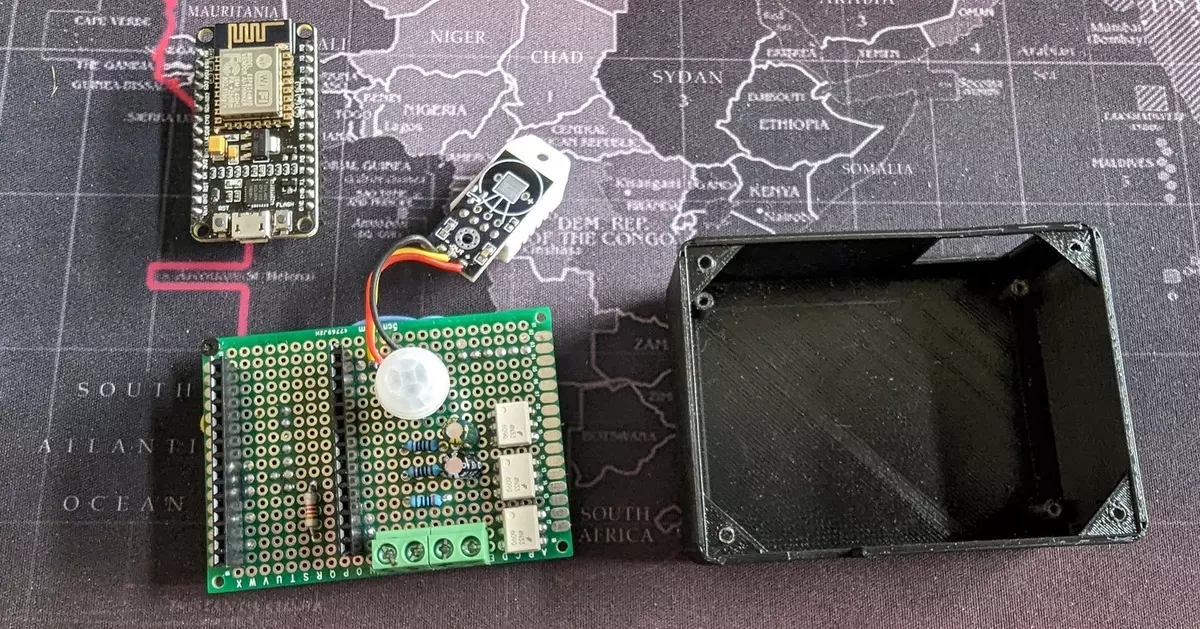
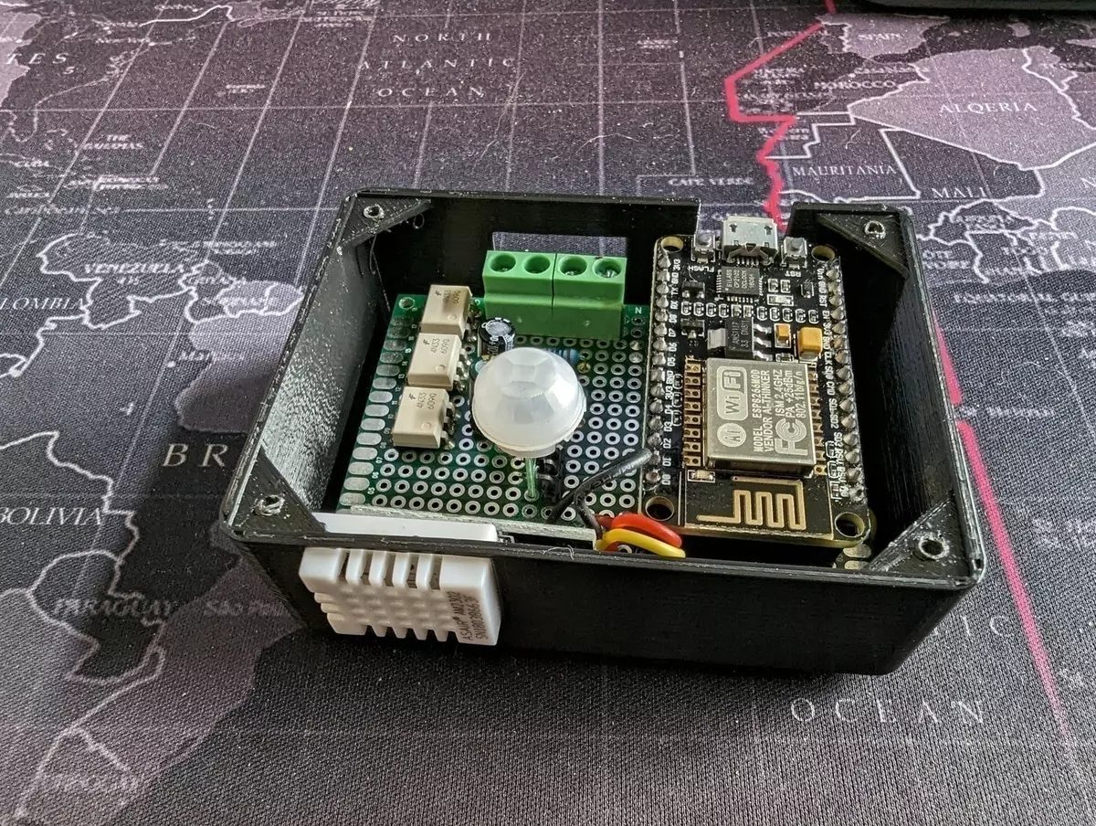
Create my own custom board to attach directly to the terminals on the opener. Originally, I was planning on using a relay module that I had used in previous project, but then discovered opto-isolators. This would make the package much more compact. I also figured I might as well add a PIR sensor and temperature sensor.
At this point, I started looking into creating my own custom PCB. Primarily, I looked at the laser printer transfer method and CNC router options. Eventually I decided to just wire a prototype board. It turned out quite messy. If I was doing it again today, I would likely look into one of the online PCB services.
The Solution
I ended up with a 3D printed case housing the following:
- NodeMCU with some custom firmware integrating with MQTT
- DHT sensor for temperature and humidity
- PIR sensor for motion
- Reed sensor to detect if door was open or closed
I wrote some custom firmware to integrate with MQTT to report state or take action. In addition, I included a reset_lock_light function in case the door lock or door lights got out of sync. I did not capture any feedback for lock or light, so if I triggered them but something went wrong, the state in Home Assistant would be incorrect. In this case, I’d simply turn both off and trigger the reset action.
The sensors and actions were created as a cover in Home Assistant. The sensor values were logged and could be charted over time. And to mee the original goal, Node Red would schedule the remote door lock during the night and send notifications if the door was left open at night.
The basic design is a negative bar and positive bus. These connect directly to the negative and positive terminals on the opener. The NodeMCU shorts the various capacitors and resistor across the bus via the opto-isolators.
The project files (including the case designed in FreeCAD) are available at https://github.com/samholton/garage-sensor
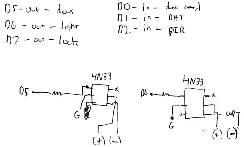 back of the napkin notes for component schematic and how opto-isolators are connected
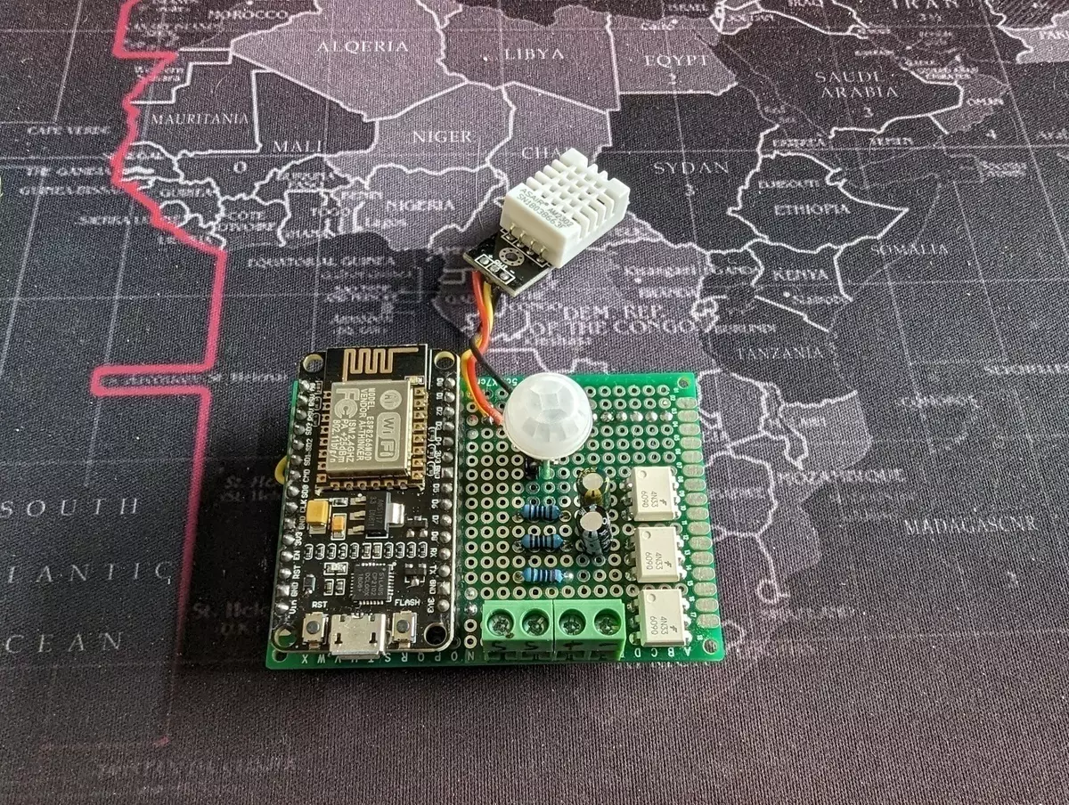 NodeMCU and sensors all wired up and ready for case
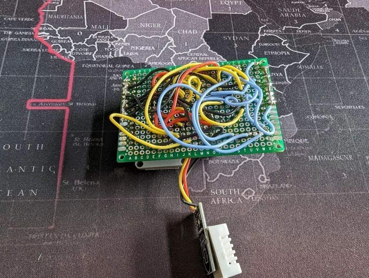 Probably should have gone with a custom PCB
 All mounted inside case
 Ready to be mounted